FUNDAMENTALS OF FACE MILLING
What is successful face milling?
Face milling is the most common milling and can be performed with a wide range of different tools. Cutters with an entry angle of 45 ° are most commonly used, but round cutters, square cutters and side cutters are also used under certain conditions. For optimal productivity, choose the right cutter (see tool selection information below).
Choice of tools
Inspection of face cutters
The diagram below shows the main scope for different concepts of cutters in terms of depth of cut, ap and feed rate, fz.
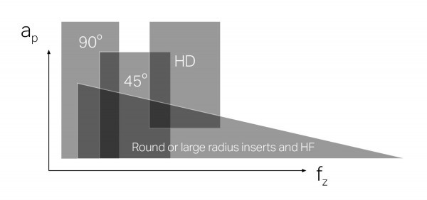
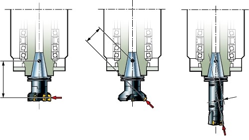
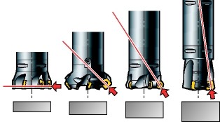
The direction of the cutting forces generated by the different angles of entry.
10 ° - 65 ° milling cutters
This wide range of cutters is mainly used for face milling, but this group also includes cutters with very small angles of entry, which are suitable for submersible milling.
45 ° cutters
- The first choice for general purposes
- Reduce vibration on long overhangs and weak layouts
- The chip thinning effect allows for higher productivity
90 ° cutters
- Thin-walled components
- Weakly attached components
- Where a 90 ° shape is required
Round insert and knives with large radius
Round insert cutters are very versatile, have excellent ramping capabilities and are used for both demanding milling processes and profiling.
- General purpose cutter
- Lots of edges on the insert
- The strongest cutting edge
- Especially suitable for heat-resistant alloys, ISO S.
- Smooth milling
Are you interested in milling services?
See our offer:
For all questions we are at your disposal:
Choice of method - an example
20-65 ° inlet angle
ADVANTAGES
• High productivity
• Optimized for face milling
• Multi-edge insertion options
WEAKNESSES
• Moderate depth of cut
HIGH PRODUCTIVITY / BASIC CHOICE
90 ° inlet angle
ADVANTAGES
• A versatile cutter that you can use for many other operations
• Low axial forces (suitable for thin-walled components)
• Relatively large depth of cut according to the size of the insert
WEAKNESSES
• Lower productivity
VERSATILE / MIXED PRODUCTION
10 ° inlet angle
ADVANTAGES
• High productivity
• Extremely high feed
• Direction of axial cutting force (favorable for spindle stability)
WEAKNESSES
• Low depth of cut
HIGH PRODUCTIVITY / PROBLEM SOLVED
How to start?
Intermittent milling of surfaces
- If possible, avoid intermittent milling (holes or slots). Such intermittent cuts, due to multiple entries and inconvenient exits, destroy the cutting edges of the tool.
- You can also reduce the recommended speed by 50% over the entire area of the workpiece that contains interruptions. The shavings will remain thin at the exit.

Face milling of thin-walled and deflected parts
- Observe the direction of the main cutting forces with respect to the stability of the workpiece and the installation
- When milling axially weak components, use a 90 ° milling cutter that directs most of the cutting forces in the axial direction.
- You can also use a milling machine for easy face milling.
- To reduce axial forces, avoid axial depths of cut of less than 0.5–2 mm.
- To get as few cutting edges as possible, use a rough-sloping cutter.
- To reduce cutting forces, use sharp, positive (-L) edges.
- Use a differential pitch cutter to solve problems.
Edging of thin sections with milling cutters
- The cutter should be placed in the middle for face milling at the edges of thin parts. The cut becomes smoother and the cutting forces are more evenly directed along the wall, reducing the risk of vibration.
- Choose a tilt cutter that has more than one insert in the cut at all times.
- Use the lightest possible cartridge geometry (light instead of medium or medium instead of heavy).
- To reduce the risk of vibration in thin-walled components, choose a smaller insert radius and a shorter parallel section.
- Use small cutting data, small cutting depth, ap and low tooth feed, fz.


Checklist and tips
- Note the stability of the tool, the size and type of spindle (vertical or horizontal) and the available power.
- Use a cutter that is 20 to 50% larger than the workpiece.
- For optimal feed, observe the maximum chip thickness when placing the cutter.
- Place the cutter in the middle to create the thinnest chip at the output.
- For favorable chip formation, i. Thick to thin shavings, use milling.
- Program the cutter to rotate in the cut or reduce the feed to get a smooth entry.


- Use milling for favorable chip formation, i. thick to thin shavings.
- Avoid entry and exit by programming the tool path.
- Frequent entry and exit from the workpiece should be avoided if possible. It can cause unfavorable loads on the edges of the knives. It is recommended that you program the tool path that keeps the cutter in full contact instead of performing multiple parallel iterations. When changing direction, turn on the small radial path of the tool so that the cutter moves and is constantly active.
Keep the cutter on at all times.

Source: Sandvik Coromant